Vortex tubes are the key to beam tube protection in heavy-ion fusion. They provide a liquid lining inside the surface of the beam tubes, collecting debris and energy from target ignitions without the long-term erosion that would result at a solid interface.
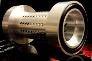
Vortex nozzle
The concept of a vortex tube is simple. A rudimentary device could be made by aiming a garden hose along the inside wall of a 4-inch pipe, such that the flow swirls around the inside surface of the pipe wall. A prototype tube has been built at Berkeley. This tube is symmetric, with flow injected through small holes tangent to the inner surface of the pipe wall.

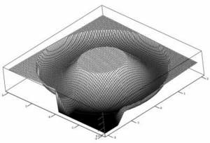
Vortex fan
When flow in the vortex layer reaches the end of the pipe, it fans out, and proper collection of the liquid leaves a clean, dry pathway through the center of the vortex tube.
An estimate of the layer thickness, t, can be derived from equating the injection area,
Ainjection = N · &pi r2,with the flow area in the layer,
Alayer = 2 · &pi [R2 - (R-t)2]where the factor of two is due to bi-directionality, r is the injection hole radius, and R is the inner pipe radius. This method only provides an approximate measure of the layer thickness, because it assumes ideal flow. It doesn't account for turbulent or viscous effects in the system.
The current experimental prototype was designed to have a layer thickness of 1/6 of the pipe radius, and measurements show that the real thickness is actually 28-30% of R, slightly more than the ideal. However, the relationship for thickness also indicates that the layer size is independent of the velocity of the flow, and experiments bear witness to this fact. No difference in the flow thickness has been observed, regardless of flow velocity, between 1-1/2 and 6 m/s, and no difference is expected at higher velocities.
It is important to note that gravity does have an affect on tube flow, as it will thicken the layer at the upstream end of the tube. This should result in a change in thickness that is proportional to the ratio of velocities, V, i.e.
Anew / Aold = Vold / Vnewdue to the requirement of mass conservation.
Currently, two methods are used for layer extraction: a reverse injection, involving holes tangent to the layer flow, or a sudden extraction using a curved 'catch tray'. Reverse injection is used upstream of the chamber, where electrical continuity of the pipe is important, and the more sudden extraction method is appropriate next to the chamber, where layer thickness is most important. Both methods are effective in diverting liquid from the layer, resulting in an end product that meets current chamber goals.
 Vortex layer extraction surface |
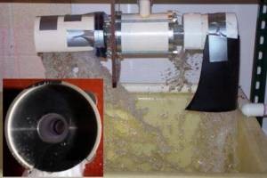 Operation of the vortex tube |