![]() The pi-coil
is
a type of coil which you have not met with before. Easily built, it
is here introduced for electronic experimenters, hobbyists and researchers.
The name "pi-coil" was chosen because there is a fixed ratio, in terms
of pi, between the wires used in the coil, for example: a coil with
a AWG 19 [1 mm] wire coiled around a AWG 7 [3.67 mm] wire and, as
well, a fixed ratio between the inner (core coil) and outer coil's
diameters and other variables. The coil is particularly useful since
its magnetic field is easily excited and so it can be useful for many
applications, some examples are: ESP and biofeedback experimentation;
proximity sensors, metal detectors; antenna tuners, oscillators, tank
circuits; and whatever your practice, knowledge and imagination will
suggest.
The pi-coil
is
a type of coil which you have not met with before. Easily built, it
is here introduced for electronic experimenters, hobbyists and researchers.
The name "pi-coil" was chosen because there is a fixed ratio, in terms
of pi, between the wires used in the coil, for example: a coil with
a AWG 19 [1 mm] wire coiled around a AWG 7 [3.67 mm] wire and, as
well, a fixed ratio between the inner (core coil) and outer coil's
diameters and other variables. The coil is particularly useful since
its magnetic field is easily excited and so it can be useful for many
applications, some examples are: ESP and biofeedback experimentation;
proximity sensors, metal detectors; antenna tuners, oscillators, tank
circuits; and whatever your practice, knowledge and imagination will
suggest.
.
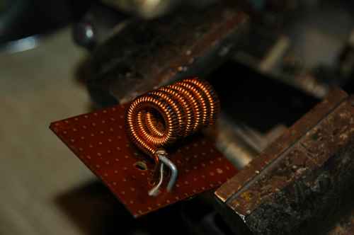
The first prototype, built in 1987.
What is needed: enameled copper wire - cable tensors (optional) - a metal rod to coil the wire around it. Time and patience!
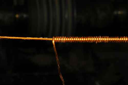
The straight wire is pulled tough between the two cable tensors, and another wire is coiled around the same.
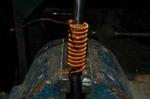
The coil thus obtained is then coiled around a firm rod.
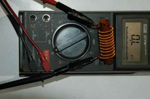
Check that there are no shorts before mounting it.
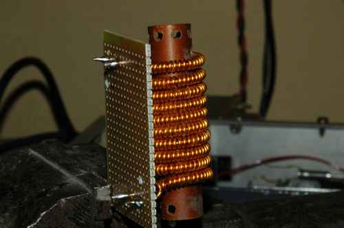
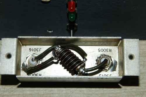
A mounting example.
Pi-coil on a toroidal nucleus. Mounted on the experimental setup seen below.
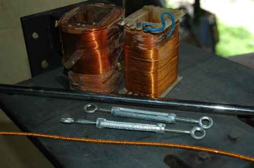
Two pi-coils. The larger one has an additional winding, the smaller has a ferrite core inside.
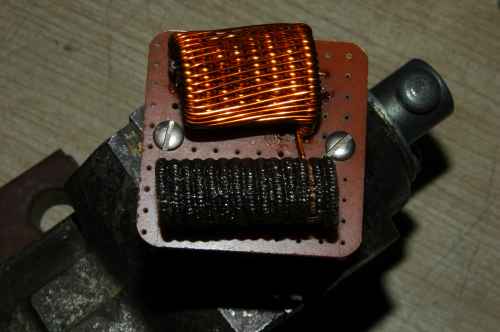
A pi-coil with multiple core-wires. The large wire is iron, the thin white wire is insulated nickel-chrome. As well, two enamel copper wires of different AWG section are inside the winding.
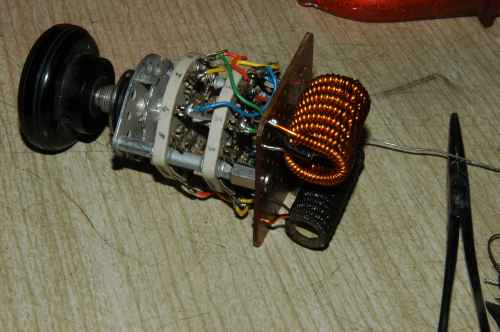
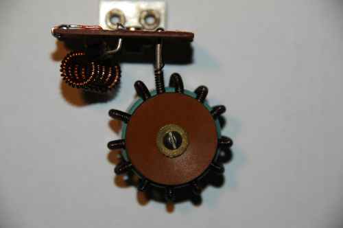
The two pi-coils shown above mounted on a rotary switch to obtain diverse configurations in experimental circuits.
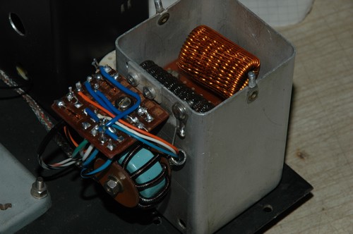
A setup for experimentation. The aluminum case contains the rotary switch depicted in the previous picture.
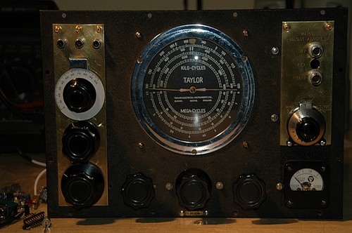
A test instrument to play with the pi-coil built around a old Taylor Radio Frequency Generator with changed heart and face.
The
![]() coil
coil
Franco
Dell'Oro ![]() Public domain
Public domain